What is PTP?
Precision Time Protocol is the common name of the IEEE standard 1588, which was first published in 2002. It defines a protocol for messages that devices can send to each other in order to synchronise their clocks throughout a network. The most recent publication of the standard achieves high accuracy timing to end devices through a combination of hardware time stamping of packets and accumulated delay calculations. Accuracy can typically be achieved to sub-microsecond figures; this makes PTP extremely suitable for applications in audio and video networks.
2008 saw a revision to the standard (IEEE 1588-20081) which takes us to PTPv2. This revision improves the robustness, precision and accuracy, but it is not backwards compatible with the 2002 standard. PTPv2 brings more features to the timing fabric of real time networks. It is an advanced timing technology, which represents the future direction of accurate time synchronisation across all industries
PTPv2 Terminology
Since PTPv2 deals with timing and sync, many of the terms reference clocks of some kind. Any device which contains a PTPv2 clock is itself simply considered a clock at the most basic level. The next distinction is between network and terminal devices. Network devices are generally considered to be pieces of equipment that make up the underlying fabric of the network: switches, routers etc. these are referred to as Boundary Clocks. Pieces of audio/video equipment, DAWs etc. (end points) are more likely to be terminal devices and these are known as Ordinary Clocks.
Dante Uses the Original PTP and Works Fine, What’s There to Know About PTPv2?
It is possible to find that various audio networking solutions each use different versions of PTP. Dante and Q-LAN used the original version 1, whilst Ravenna, which is widely used in the broadcast and studio world, uses version 2.
With Dante systems, PTPv1 is used to synchronise clocks of all the audio device endpoints. This is an automatic process whereby a Grand Master is elected (based on your preferred master settings for example) and then the slave devices receive the clock sync messages. In order to give PTP some priority on the network (as it travels through the switches connecting your devices), Dante uses Quality of Service (QoS) markings to designate PTP messages as having the highest priority. Clock precision can still be affected by the volume of traffic and how much contention there is for priority. Thus; PTP clock messages can get stuck and delayed in the backbone; in the switches between your devices.
As previously mentioned, v2 is not backwards compatible with v1. When the AES67 interoperability standard was published, it mandated the use of PTPv2. As more manufacturers have sought to bring AES67 interoperability and support to their products, they have harmonised their PTP implementations or included other mechanisms in order to adhere to the standard. As an example, QSC Q-LAN updated to PTPv2 approximately two years ago.
At the very least, Dante devices currently support PTPv1; those manufacturers who have released AES67 enabled Dante devices support both versions, and many non-Dante AES67 devices support v2 only. It is possible for a Dante network using PTPv1 to exchange AES67 streams with devices using PTPv2. In that scenario, one AES67-enabled Dante device needs to act as the Boundary Clock, bridging the PTPv1 and PTPv2 clock domains. As shown in the illustration below, two clock domains (two audio clock territories, Dante and AES67) will get created across the different devices.
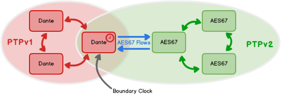
*Yamaha has more information on this subject in their document: Connecting Yamaha Dante devices with other AES67 devices http://download.yamaha.com/file/68829
Master Clock Selection
In a PTPv2 network, one clock is elected as the Grandmaster. The Grandmaster is the clock from which all other clocks will derive their time; this is similar to a master clock that distributes Word clock in a digital audio setup.
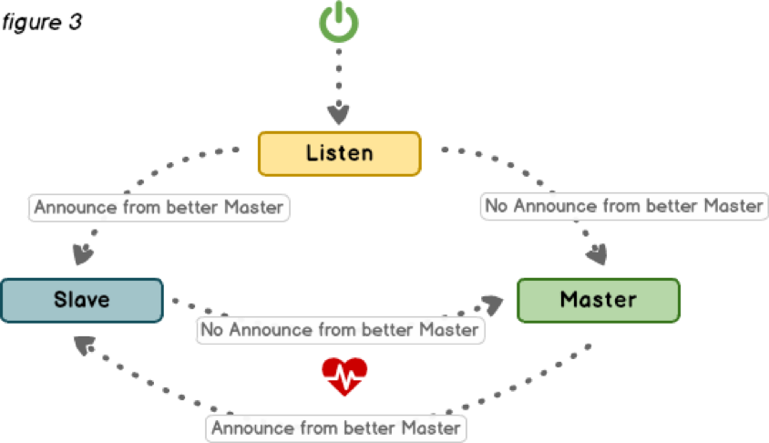
Upon initialisation, a PTPv2 device starts in the ‘listen’ state whereby it is listening for PTPv2 announce messages on the network segment that it is connected to. If no messages arrive after a predetermined length of time (know as the Announce Timeout Interval) the device acts as a master. If upon startup an announce message arrives, the device concludes that there is already a master present and it will behave as a slave, provided that its own clock is not of a superior quality to that of the master’s.
Announce messages also include information about the quality of the clock sending them. If a device receives an announce message and determines that its clock is more accurate, then it will assume the role of master and the other will revert to a slave. This serves to ensure that the best clock on the segment is master as well as providing redundancy, in the case that a master clock goes offline due to failure. When other clocks notice the absence of a master, they will begin to announce their presence and the most accurate will assume the role of master. This process is known as the Best Master Clock Algorithm (BMCA). It is also possible to stipulate which device should be the master (for example, the “Preferred Master” in a Dante / AES67 system which acts as the boundary clock for both domains). Figure 3 illustrates a simplified cycle of the BMCA.
PTPv2 Accuracy
PTPv2 is capable of using hardware to solve some of the timing jitter encountered as packets move around the network and through different devices. All network devices take some measure of time to process and queue the bits flowing through them, in much the same way that latency is introduced in an audio path due to A/D conversion.
Knowing the duration of this ‘residence time’ and correcting for it enables the synchronisation to be that much tighter. By virtue of special hardware, timestamps are generated from a device’s local clock that are used in the messages that PTPv2 exchanges. Devices can work out not only the time it has taken for messages to arrive but also update their time, or that of messages they send, to compensate for the delays experienced by packets as they are processed internally.
This is also something which differentiates a Transparent Clock from a Boundary Clock. A switch acting as a Boundary Clock will use PTPv2 to update its own time and apply that to packets that it sends. A Transparent Clock will calculate how long packets have spent inside of itself and add a correction for that to the packets as they leave. In that sense, the switch becomes ‘transparent’ in time, as if it is not contributing to delay in the network.
PTPv2 uses a series of messages to synchronise the time between clocks. The master clock sends a Sync message to the slave clock and makes a note of the timestamp t1 as the message leaves. When the slave clock receives this message, it too makes a note of when it arrived, t2. The master clock also sends a Follow_Up message to the slave that contains the value it noted for t1. The slave sends a Delay_Req message to the master and makes a note of when it was sent, t3. When the master gets this message, it makes a note of the time it was received, t4, and sends that value back to the slave in a Delay_Resp message. The slave clock now possesses all four timestamps that can be used to compute the offset of the slave clock relative to the master, and the propagation time between the two clocks.

PTPv2 Support in GigaCore Switches
In order to have the best synchronisation in you network, it helps if the switches (and routers) passing your data also understand PTPv2 as well, not just the end devices. It is perfectly possible to deploy an audio network using switches that don’t support PTPv2. However; in certain scenarios or in mixed applications, it may be a requirement in order to avoid problems.
PTPv2 support in switches can also ensure that sync packets, which could have similar priority or higher than streaming data (Dante vs AES67), will still be correct when delayed by queuing or by a sudden surge of network traffic. Timestamping makes the corrections accurate and thus keeps the jitter low; resulting in reduction of QoS conflicts.
Luminex Network Intelligence has been involved in configuring and validating PTPv2 support for different audio over IP solutions including AES67 with industry specialists such as RAVENNA. The GigaCore family of switches ship pre configured and validated with PTPv2 support out of the box. These switches use hardware timestamping for the forwarding time measurements with a divergence of only +/- 20ns. We can actually say that PTPv2 switches undoubtedly contribute to making synchronisation in our networks better.
The performance of the switches is just one aspect of the sync situation; the resulting clock sync accuracy also has a lot to do with how well the PTPv2 algorithms have been implemented in all other contributing devices.
PTP Profiles
PTPv2 profiles allow standards bodies such as the AES and SMPTE to adapt the PTPv2 implementation to fit a particular application. A profile defines which aspects of PTPv2 are included or excluded and configurable ranges and defaults for the application.
PTPv2 includes a default profile and there are a few other profiles relevant to networked audio and video, the main ones being:
- The Media profile of AES67
- The SMPTE profile of SMPTE ST 2059-2
Particular attention needs to be paid in order to ensure interoperability between devices that conform to different profiles. Detailed information on the recommended parameter choices for AES and SMPTE interoperability can be found in the AES document AES-R16-20162.
The IEEE 802.1AS3 (gPTP) standard qualifies as a PTPv2 profile specific to AVB implementations. It simplifies PTPv2 and defines synchronisation over other media besides Ethernet.
The PTPv2 Hierarchy
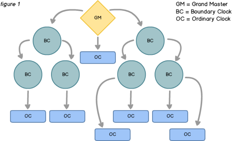
In a PTPv2 network, one clock is elected as the Grandmaster. Clock synchronisation occurs between adjacent clocks in a Master/Slave relationship. A device can be a slave as well as acting as a master to other clocks further downstream. This continues until there are no clocks left which are both slave and master and the remaining clocks at the bottom of the hierarchy are only slaves. Transparent Clocks do not contribute to the master/slave hierarchy, although they do serve to improve synchronisation by forwarding PTPv2 messages and providing corrections to take account of the time that packets take to travel through them.
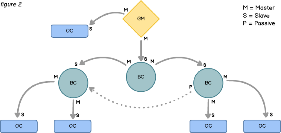
In practice, there are likely to be redundant links between some of the Boundary Clocks, creating a mesh. It is, therefore, necessary for this mesh layout to be hidden or ‘pruned’. One method of achieving this is by pruning PTPv2 in conjunction with a protocol that can do this for us, for example, the Spanning Tree Protocol (STP). If STP is not being used, the BCs will put some of their ports into a ‘passive’ state and prune the topology in that way. The diagram figure 2 illustrates the master/slave relationship and the dashed line represents the link, which has been pruned to maintain the tree topology.
References
- 1588-2008 IEEE Standard for a Precision Clock Synchronization Protocol for Networked Measurement and Control Systems.
http://standards.ieee.org/findstds/standard/1588-2008.html - AES-R16-2016: AES Standards Report – PTP parameters for AES67 and SMPTE ST 2059-2 interoperability.
http://www.aes.org/publications/standards/search.cfm?docID=105 - 1AS-Rev – Timing and Synchronization for Time-Sensitive Applications
http://www.ieee802.org/1/pages/802.1AS-rev.html - P1588 Working Group – charged with the maintenance and any future revisions of the IEEE 1588 Standard.
https://ieee-sa.imeetcentral.com/1588public/